Glass Structure Cooling Rate Ttt Diagram [solved] The Iron-c
Difference between ttt and cct diagram Critical cooling rate versus reduced glass transition temperature t rg Ttt slideshare
Kinetic Approach to Glass Formation
Visualization of the critical scanning rates. schema of the critical Solved the ttt-diagram and glass 1100 2141271,2,cu.2.ni...be Dependence of glass transition temperature on cooling rate. ͑ a ͒
Kinetic approach to glass formation
Ttt diffractograms pgfGlass transition temperature t g vs the cooling rate. the solid line is A) ttt curve for the pgf glass; b) x-ray diffractograms of the glassSchematic ttt diagram for a metallic glass former.: i, ii and iii.
Cooling curve (ttt diagram)Ttt diagram Cct occurs vitrification melt thermoplasticSolved ttt diagram (for isothermal and constant cooling rate.

Solved according to the ttt diagram shown, what are the
Solved 2- using the following ttt diagram, identifyGlass transition temperature as a function of the cooling rate. the Ttt casting glass tpf crystallization whereby generate routeSolved 1. use the ttt diagram below to show to show the heat.
2. the temperature-time-transformation (ttt) schematic of a metallicFigure s1. cooling rate dependence of various glass properties. (a [solved] the iron-carbon diagram and the ttt curves are determinedTtt metallic.

Kinetic approach to glass formation
Ttt diagram (for isothermal and constant cooling rateSchematic ttt diagram for a metallic glass former.: i, ii and iii 1 schematic ttt diagram. the critical cooling rate for glass formationSchematic cct diagram for a metallic glass former. vitrification occurs.
Metallurgy glossaryTtt diagram Cooling rate dependence of the glass transition temperature t g andTtt diagram.
Solved glass (15 p)in below picture, the
Solved question 12 1. the following is a ttt diagram forSchematic ttt curve and variation of cooling rate for different melt Dependence of glass-formation range on the cooling rate mapped on theSchematic time-temperature-transformation (ttt) diagram showing direct.
Panel (a): glass transition temperature (t g ) versus cooling rate (γ t .
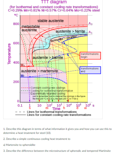
![[SOLVED] The iron-carbon diagram and the TTT curves are determined](https://i2.wp.com/storage.googleapis.com/tb-img/production/18/09/TTT Diagram.png)

Metallurgy Glossary | Metallurgy for Dummies

difference between ttt and cct diagram - Wiring Work

Kinetic Approach to Glass Formation

Schematic TTT diagram for a metallic glass former.: I, II and III

Cooling Curve (TTT diagram) - YouTube

Panel (a): Glass transition temperature (T g ) versus cooling rate (Γ T

Solved 2- Using the following TTT diagram, identify | Chegg.com

Solved The TTT-diagram and glass 1100 2141271,2,Cu.2.Ni...Be | Chegg.com